DL9SEC
German Amateur Radio StationJN48VP • DOK P62
DL9SEC DDS-VFO
with DRM receiver frontendIntroduction
This project started in the middle of 2003, when I read some articles about DRM (Digital radio mondiale) and found the website of Christoph Petermann (DF9CY), where he published some schematics for a DRM demonstration receiver.
Because of my interests as radio amateur and engineer, I decided to build my own microcontrolled direct conversion receiver with a DDS-VFO. The first version of this receiver (downmixing the RF to a 12kHz IF) includes the microcontroler (with LCD, rotary encoder and keypad), the DDS-unit, the mixer stage and the 12kHz-amplifier. The software for the MCU was very simple with a fix table of DRM station frequencies. It works fine for a first attempt, but there was a lot room for improvements...
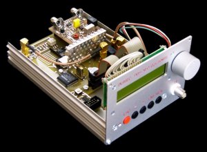
Fig. 1: View of the DDS-VFO
Overview
1. The DDS-VFO

Fig. 1: Block diagram of the DDS-VFO
Features of the DDS-VFO:
- • Frequency range from 0,500.0MHz to 39,999.9MHz
- • Possible frequency steps are 100Hz, 1kHz, 10kHz, 100kHz, 1MHz
- • Power range from -40dBm to +10dBm (-40dBm, -30dBm, -25dBm, -20dBm, -15dBm, -10dBm..+10dBm in 1dB steps)
- • Harmonics rejection at +10dBm output power better than 40dBc
- • Microcontrolled (firmware flashable)
- • 16x2 LC display with LED backlight
- • 5 button keypad and rotary dial
- • Indicator LED and beeper
- • Generator and receiver mode
- • Adjustable IF (1kHz..460kHz) in receiver mode
- • Fixed output power (+7dBm) in receiver mode
- • "One-touch" switchable LO shift (above or below fr) in receiver mode
- • Automatic save of the all parameters after 3 seconds
- • Remote frequency control via RS232 (acts as a Yaesu FT-817)
- • Slot for extension (e.g. the DRM receiver frontend)
2. The DRM receiver frontend
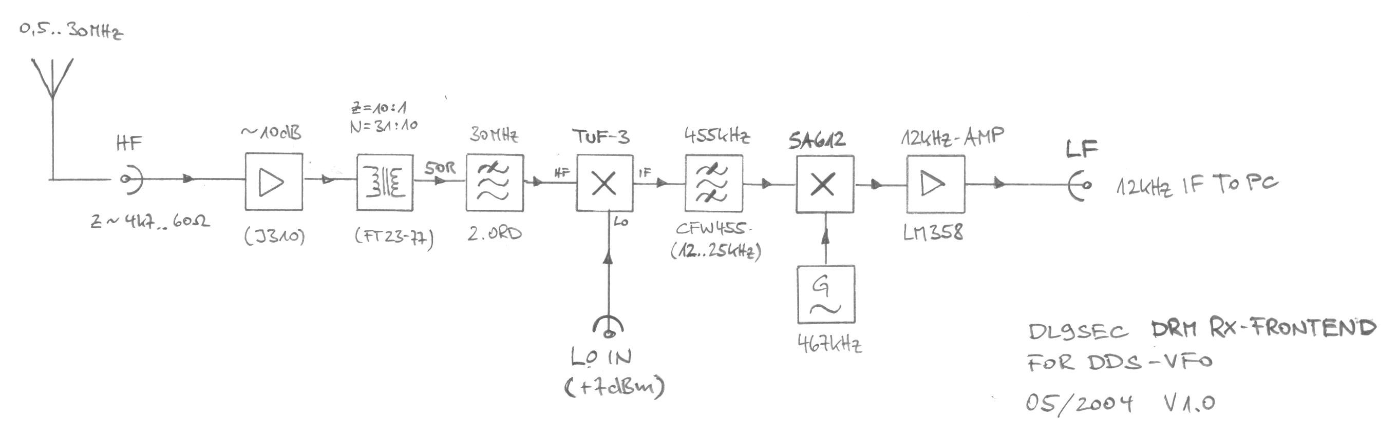
Fig. 2: Block diagram of the DRM receiver frontend
Features of the DRM receiver frontend:
- • Input frequency range from 0,5MHz to 30MHz
- • FET preamplifier for short antennas
- • Double superhet (1st IF 455kHz, 2nd IF 12kHz)
- • Output amplifier and buffer for direct connection to a PC soundcard (line in)
- • For use with a DRM decoding software (e.g. DReaM)
Operation
1. The front panel
Fig. 1 shows the front panel of the device which contains:
- • the 16x2 character LC display with backlight
- • the rotary dial (frequency and power adjustment)
- • • the red indicator LED (flashes if parameters are stored)
- • the ESC (escape) button
- • the < (cursor left) button
- • the > (cursor right) button
- • the ENT (enter) button
- • the MEN (menu) button
- • the HF output jack of the generator (BNC)
A detailed description of the different modes of oeration can be found in the folowing sections.
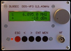
Fig. 1: The front panel of the DDS-VFO
2. Setup with defaults
After the first programming of the microcontroller, the content of the EEPROM has to be filled with reasonable values. The firmware includes a setup routine, that can be executed by the following steps:
- • Turn off the power supply or press and hold the reset button
- • Press and hold the ESC and MEN button at the same time
- • Release the reset button or turn the power supply on
- • Release the ESC and MEN button
The firmware starts with the screen, shown in fig. 2. These are the default values:
- • DDS-VFO set to receiver mode
- • Receiving frequency (fr) set to 10,000.0MHz
- • IF set to 455kHz
- • LO above receiving frequency
- • Cursor set to the 100Hz position
- • Output power for generator mode set to -40dBm
![]()
Fig. 2: Setup screen of the DDS-VFO
3. Startup of the DDS-VFO
The DDS-VFO starts with the screen, shown in fig. 3. The backlight is turned on smoothly and a double beep sounds.
If this screen appears, all the parameters are read from the EEPROM. After a delay of one second the program continues with the last saved settings or the default settings after a setup.
![]()
Fig. 3: Startup screen of the DDS-VFO
4. Receiver mode
After performing a setup, the device starts in receiver mode. This mode is indicated by an antenna symbol (![]() ). In this mode, the DDS-VFO is used as tuneable local oscillator (LO) for the first mixer stage of the receiver. The internal relay switches the HF from the front panel jack to the internal jack "RX". The output power of the DDS is held constant at +7dBm over the whole frequency range. The DDS output frequency differs from the displayed frequency by the value of the intermediate frequency (IF):
). In this mode, the DDS-VFO is used as tuneable local oscillator (LO) for the first mixer stage of the receiver. The internal relay switches the HF from the front panel jack to the internal jack "RX". The output power of the DDS is held constant at +7dBm over the whole frequency range. The DDS output frequency differs from the displayed frequency by the value of the intermediate frequency (IF):
- •
 means, that the output frequency is above the displayed frequency (see fig. 4)
 - •
 means, that the output frequency is below the displayed frequency (see fig. 5)
This feature is implemented because of the missing image or mirror frequency (fr +2*IF) rejection of the receiver frontend (untuned input circuit). If a station is transmitting at this mirror frequency, the IF shift can be toggled to get a (maybe) better signal of the wanted DRM-station.
In the lower line of the display, a frequency bar with the coarse frequency information is shown.
![]()
Fig. 4: DDS-VFO in receiver mode
with LO above fr
![]()
Fig. 5: DDS-VFO in receiver mode
with LO below fr
The following list shows, what can be done in receiver mode:
- • Turn the dial clockwise to increase the frequency
- • Turn the dial couterclockwise to decrease the frequency
- • Press ESC to switch to generator mode
- • Press < to move the cursor one digit to the left
- • Press > to move the cursor one digit to the right
- • Press ENT to toggle between "LO above fr" and "LO below fr"
- • Press MEN to enter the "IF Adjust" menu
In the "IF Adjust" menu (see fig. 6) the IF shift can be set between 1kHz and 460kHz in steps of 1kHz with the dial. By pressing ESC the displayed IF will be applied and the screen is switched back to receiver mode.
The receiving frequency can also be changed by remote from the PC (e.g. by DReaM). The device acts as a Yaesu FT-817, but only for frequency change information. A remote access is indicated by the ![]() symbol, as long as data is transferred (see fig. 7).
symbol, as long as data is transferred (see fig. 7).
A change of the mode, frequency, cursor position, IF shift or IF will cause the device to store the actual parameters to the EEPROM after 3 seconds of inactivity. So the write cycles to the EEPROM are reduced.
![]()
Fig. 6: IF adjust menu in
receiver mode
![]()
Fig. 7: Remote frequency control
in receiver mode
5. Generator mode
The generator mode is indicated by an double sine symbol (![]() ).
).
In this mode, the DDS-VFO is used as high frequency (HF) generator. The internal relay switches the HF from the internal jack "RX" to the front panel BNC jack. The DDS output frequency equals the displayed frequency.
Instead of the frequency bar, the output power is shown. This output power can be changed with the dial in the following steps: -40dBm, -30dBm, -25dBm, -20dBm, -15dBm, -10dBm..+10dBm (in 1dB steps). The choosen power is held constant over the whole frequency range within ± 0,3dBm by a calibrated table (1MHz steps).
The following list shows, what can be done in receiver mode:
- • Turn the dial clockwise to increase the frequency or power
- • Turn the dial couterclockwise to decrease the frequency or power
- • Press ESC to switch to receiver mode
- • Press < to move the cursor one digit to the left
- • Press > to move the cursor one digit to the right
Remote control is possible like in receiver mode (see fig. 9).
![]()
Fig. 8: DDS-VFO in generator mode
![]()
Fig. 9: Remote frequency control
in generator mode
© 2017-2020 Thorsten Godau DL9SEC • Powered by ALL-INKL.COM • Favicon by Icons8
© 2016 Static Flat Ui kit. All rights reserved | Design by W3layouts